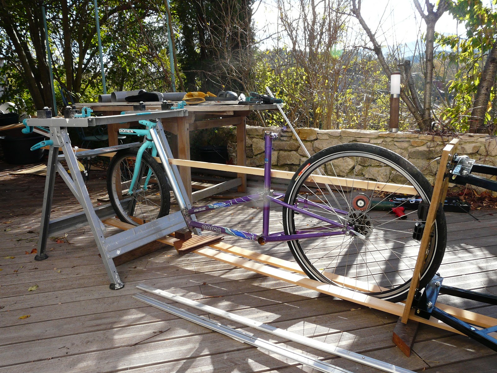
So here is my faithful, all-purpose frame being used to prototype a FWD version. One of the first things to strike the eye is how the FWD removes all that lengthy chain and its hard-to-manage chain line running the whole length of the bike. I personally find it both functionally and aesthetically appealing (despite what you may think of the rest of the bike!).

 The use of FWD does introduce its own challenges, however. Firstly it requires an intermediate idler to divert the chain line from the near horizontal to the near vertical. To avoid pedal-induced steering torque, the drive chain line from the idler must lie parallel with, and as close as possible to the steering axis. Initially I used a development of my early home-built RWD idlers, using a large cassette cog cut out of a cassette block and bolted onto a roller skate wheel body, which was mounted with a 6mm bolt to a box section welded at the BB boom/steering head junction. (The roller skate wheel has a very nice quality, low friction bearing for smooth rolling; see the post on Idlers for further discussion.) Very quickly one discovers that a potential issue with FWD idlers is their tendency to suck in the hairs on your leg as your upper thigh passes by as you pedal. This is not a desirable feature! I cut out a plastic disc and fixed it to the outside of the idler to prevent this. It worked OK.
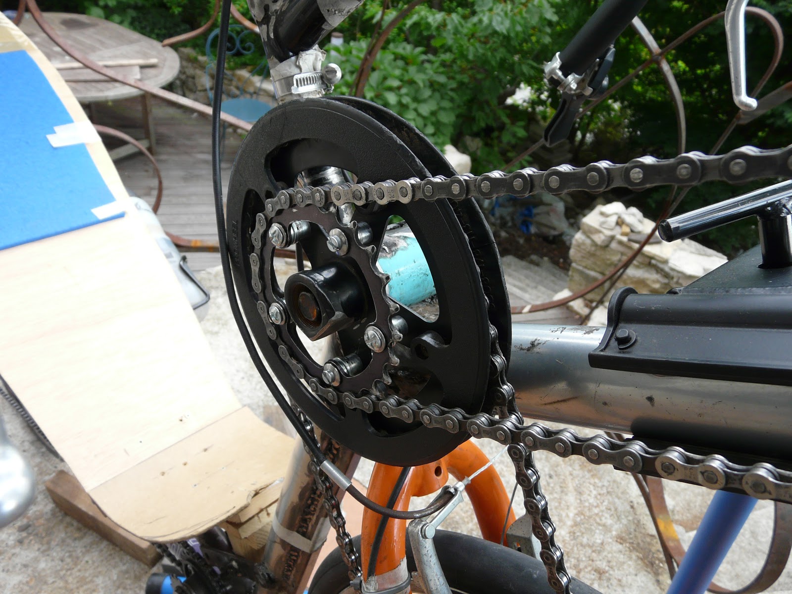
However, the limits of my roller skate-bodied idler soon became apparent when my enthusiastic pedaling ripped the cassette cog from the skate wheel body. Something beefier was needed, so I turned to the next thing that came to hand in my box of bits... a second bottom bracket. I welded a BB housing cut out of another bike in place of the box section unit at above the BB boom, and fitted a BB into it with a 34 tooth single ring chainset taken from a child's bike with the crank ground off. This is not only a bigger diameter - and hence more efficient (see later discussion) - but it comes with its own plastic guard. Brilliant!

The intermediate idler takes care of the drive side chain line, but we also need to manage the return side chain line. Unlike the drive side chain, which acts to transfer the significant pedal forces to the front wheel hub, the return line is under essentially no tension (only that from the sprung derailleur arm). I chose to use a derailleur cog as the return idler because it is small, light, and well-suited to the purpose. The issue with the return chain line is that undergoes significant lateral movement as the front wheel is steered left or right, and this can lead to interference with the front tyre.
Note that this chain interference is not symmetrical. That is, when the fork is steered to the left it is the upper part of the tyre behind the fork that will come into contact with the drive chain line running up the back of the right fork. Conversely, when steering to the right it is the upper part of the tyre in front of the fork that will contact the return chain line. In general, if the drive chain line is well placed in relation to the fork leg (more on that in the discussion section), it is the steering arc to the right that is most limited by chain interference.
 A keen eye will have noticed a key difference in the return idler mounting between the photo above and this photo here. Above, the idler is mounted to the BB boom, while here it is attached to the fork leg. In both cases it is beneficial to mount the return idler as close to the fork leg as is practically possible and above the tyre, since this allows a greater degree of steering arc before the tyre contacts the return chain. But, significantly, when the return idler is attached to the fork leg it also moves laterally with the fork when steering; this means that the fork can be steered even further to the right before the tyre contacts the chain.
While this fork-mounted idler does wonders for the steering arc, it introduces a new issue of its own; torque steer. Essentially, although the return chain is under significantly less tension than the drive side, the light tension in the chain between the return idler and the front chain ring (due to the derailleur spring) is sufficient to "tug" on the right fork leg and thereby introduce a small steering torque to the left. In practice this is not a huge problem, and for anybody seeking a tighter turning circle for their bike it might be a good solution. However, it does mean that straight line hands-off riding is compromised, assuming that the bike's geometry is such that this would otherwise be possible.
A further issue with a FWD version of a small front-wheeled Low Racer is that of gear ratios; or rather - as the late, great Sheldon Brown explains it best - "gain ratios". (See Gain Ratios). Essentially, what this means is that the smaller driving (front) wheel cannot propel you at the same speed as a larger RWD driving wheel when pedaling in the same gear selection at the same cadence (and, to be really precise, with the same length cranks). A common solution to this issue is to purchase an especially large chain ring - typically 60, 62, or even 65 teeth - to replace the standard 52 or 53 tooth large chain ring.
However, this is a BIG ring, both functionally and aesthetically displeasing (at least to me). An alternative is to effectively "step up" the gear ratio at the intermediate drive idler. This requires two elements.
 Firstly, the drive idler is modified to comprise an "input" and an "output" cog. The ratio of teeth on these cogs determines the step-up of the overall gear ratio between the crank and the cassette.
Second, a chain tensioner needs to be installed in the return line between the drive idler and the chainset. Here, I've adapted my trusty derailleur cog unit to add the tension at the chain ring by simply hanging it by an elastic cord. This was the simplest and quickest method I found to hand in order to test out the step-up concept, but in practice this tensioner device is not appropriate; it has too much vertical and horizontal play, and being so close to the chainset it creates problems when changing rings.
Firstly, the drive idler is modified to comprise an "input" and an "output" cog. The ratio of teeth on these cogs determines the step-up of the overall gear ratio between the crank and the cassette.
Second, a chain tensioner needs to be installed in the return line between the drive idler and the chainset. Here, I've adapted my trusty derailleur cog unit to add the tension at the chain ring by simply hanging it by an elastic cord. This was the simplest and quickest method I found to hand in order to test out the step-up concept, but in practice this tensioner device is not appropriate; it has too much vertical and horizontal play, and being so close to the chainset it creates problems when changing rings.
The total step-up system looks like this.
Once again I had the same reliability problems with the fixing of the cogs to the skate wheel body, as mentioned above, so when I decided to weld a bottom bracket unit to the frame to serve as the idler mount I bolted the secondary "output cog" to the idler pulley as below.

This step-up idler gear was more reliable, but both systems suffered the same conceptual problem; that of their width. The issue of "hair suck" when using a single idler gear is essentially due to the "Q factor" of the idler unit; a narrower unit with a lower Q factor presents less chance of contact with the thigh when pedaling. By filing the taper on the end of the BB square axle I was able to place the 32 tooth chainring idler as close as possible to the frame tubing at the steering head/BB boom mounting. This gave a sufficiently low Q factor that hair suck or "thigh rub" was not a problem. However, by adding a secondary gear to this unit, the width is increased noticeably and this forces an unnatural pedaling action with the knees parted in a bow-legged manner to avoid contact between the idler and the thighs. For this reason I finally decided to abandon further exploration of the step-up drive idler concept.
 It was noted above that my quick fix tensioning idler on an elastic cord was, at best, adequate for testing the concept using a single front chainring, but could not follow the chain as it was shifted across different chainrings. But that's not to say that a better designed idler could not work, but it would probably need to act on the return line of the "input" chain as it leaves the step-up gear idler.
It's worth mentioning that an alternative - and conceptually rather elegant - step-up gear solution exists, where the "input" chain is moved to the LHS of the BB boom. In this method a single chainring at the pedals drives the input gear of the step-up drive gear unit, with the chain loop tensioned as for a single speed or "fixie" road bike. The entire input drive system - chain ring, input step-up gear, and chain loop - is swapped to the LHS of the BB boom, and the single output gear on the step-up drive is replaced by a two or three ring chainring set on the RHS. A front derailleur unit is added on the RHS at this chainset to shift the chain across the output gear rings, and - together with the cassette on the front hub - the output drive chain loop acts precisely as the chain drive on any upright bike to provide the full range of gears.
 To best visualise this, in the photo here, imagine simply that the crankset+upper chain+small drive idler gear are swapped as a unit to the other side of the BB boom, while the single large drive idler is replaced by multiple chainrings+front derailleur.
Perhaps it is the symmetry of having two chain lines on either side of the BB boom that appeals to me, but this system is also not without its own issues. Firstly, inverting the crankset means that the pedaling action will cause its BB to unscrew from its frame mount. This is easily resolved by simply flipping the BB mount when it's welded to the boom. The second issue is once again that of Q factor, and here there is not only a 2 or 3 ring drive gear unit between the frame and the right thigh, but the front derailleur as well. The potential for "thigh rub" and "leg hair suck" is greatly increased and can render the pedaling action unacceptably painful. A very low seat and fairly low crankset, combined with a high drive gear unit, may allow the knees to pass below the drive unit as so avoid this problem, but this imposes significant constraints on the rider's position and frame design which might not be acceptable. Nevertheless, I know of at least a couple of riders who employ this system on their (very) Low Racer FWDs.


 The main objective of this wooden wonder was to see what fork angle and trail I should use to make a good handling bike. This was easy to adjust by simply loosening the four bolts on the wooden head tube clamp. I spent a lot of time playing with these parameters, and - despite knowing from bike magazine journalists how just a degree or two difference can radically transform a MTB from a nimble handling XC bike into a rock stable Downhiller - I began to get the impression that quite large variations didn't actually seem to make any difference.


 My optimism for the advancement of objective scientific study and analysis of the variables that govern recumbent pedaling efficiency and performance is rapidly diminished by the realisation that I am missing any means to measure key factors such as power input by the rider or resistance overcome at the rear wheel. This technical deficiency renders any analysis of changing the parameters of my laboratory test bed no more than a subjective impression. For objective measures I would require at least a power meter at the rear wheel and, preferably, a second on the crankset to be able to study the power in/power out ratios.


 The use of FWD does introduce its own challenges, however. Firstly it requires an intermediate idler to divert the chain line from the near horizontal to the near vertical. To avoid pedal-induced steering torque, the drive chain line from the idler must lie parallel with, and as close as possible to the steering axis. Initially I used a development of my early home-built RWD idlers, using a large cassette cog cut out of a cassette block and bolted onto a roller skate wheel body, which was mounted with a 6mm bolt to a box section welded at the BB boom/steering head junction. (The roller skate wheel has a very nice quality, low friction bearing for smooth rolling; see the post on Idlers for further discussion.) Very quickly one discovers that a potential issue with FWD idlers is their tendency to suck in the hairs on your leg as your upper thigh passes by as you pedal. This is not a desirable feature! I cut out a plastic disc and fixed it to the outside of the idler to prevent this. It worked OK.
 A keen eye will have noticed a key difference in the return idler mounting between the photo above and this photo here. Above, the idler is mounted to the BB boom, while here it is attached to the fork leg. In both cases it is beneficial to mount the return idler as close to the fork leg as is practically possible and above the tyre, since this allows a greater degree of steering arc before the tyre contacts the return chain. But, significantly, when the return idler is attached to the fork leg it also moves laterally with the fork when steering; this means that the fork can be steered even further to the right before the tyre contacts the chain.
 Firstly, the drive idler is modified to comprise an "input" and an "output" cog. The ratio of teeth on these cogs determines the step-up of the overall gear ratio between the crank and the cassette.

 It was noted above that my quick fix tensioning idler on an elastic cord was, at best, adequate for testing the concept using a single front chainring, but could not follow the chain as it was shifted across different chainrings. But that's not to say that a better designed idler could not work, but it would probably need to act on the return line of the "input" chain as it leaves the step-up gear idler.
  To best visualise this, in the photo here, imagine simply that the crankset+upper chain+small drive idler gear are swapped as a unit to the other side of the BB boom, while the single large drive idler is replaced by multiple chainrings+front derailleur.


